
💡 What is an ERD?
Using ERD in DB engineering guarantees you to produce high-quality DB design to use in DB creation, management, and maintenance.
Then first of all, what is an Entity Relationship Diagram?
ER Diagram, or ER model, is a type of structural diagram for use in relational DB design in terms of concept visualization. An ERD contains different symbols and connectors that visualize two important information: The major entities within the system scope, and the inter-relationships among these entities.
And that's why it's called 'Entity' 'Relationship' diagram!
💡 ERD notations
📌 Entity ( == Table )

definable things or concepts within a system, such as people/roles (e.g. Student), objects (e.g. Product), concepts (e.g. Profile) or event (e.g. Transaction), etc
📌 Entity Attributes ( == Column )

An attribute is a property or characteristic of the entity that holds it.
An attribute has a name that describes the property and a type that describes the kind of attribute it is, such as varchar for a string, and int for integer.
When an ERD is drawn for physical database development, it is important to ensure the use of types that are supported by the target RDBMS.
- Primary Key
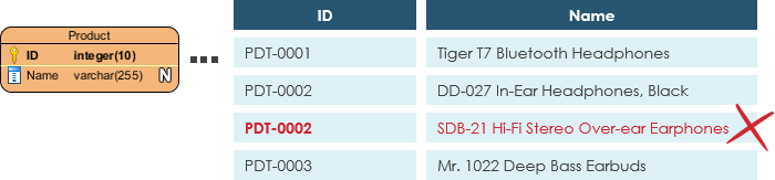
Also known as PK, a primary key is a special kind of entity attribute that uniquely defines a record in a database table. In other words, there must not be two (or more) records that share the same value for the primary key attribute according to the example above. - Foreign Key
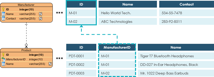
Also known as FK, a foreign key is a reference to a primary key in a table. It is used to identify the relationships between entities. Note that foreign keys need not be unique unlike the primary key. Multiple records can share the same values. The example above shows an entity with some columns, among which a foreign key is used in referencing another entity.
📌 Relationship
A relationship between two entities signifies that the two entities are associated with each other somehow. For example, a student might enroll in a course. The entity Student is therefore related to Course, and a relationship is presented as a connector connecting between them.
Cardinality defines the possible number of occurrences in one entity which is associated with the number of occurrences in another. For example, ONE team has MANY players. When present in an ERD, the entity Team and Player are inter-connected with a one-to-many relationship.
- One-to-One Cardinality
It is mostly used to split an entity in two to provide information concisely and make it more understandable.
- One-to-Many Cardinality
It refers to the relationship between two entities X and Y in which an instance of X may be linked to many instances of Y, but an instance of Y is linked to only one instance of X.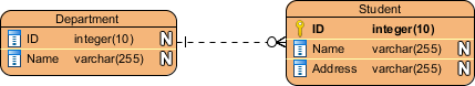
- Many-to-Many Cardinality
It refers to the relationship between two entities X and Y in which X may be linked to many instances of Y and vice versa. Note that a many-to-many relationship is split into a pair of one-to-many relationships.
💡 How to draw ERDs?
- Make sure you are clear about the purpose of drawing the ERD and the right level of detail data models.
- Make sure you are clear about the scope to model.
Knowing the modeling scope prevents you from including redundant entities and relationships in your design. - Draw the major entities involved in the scope.
- Define the properties of entities by adding columns.
- Review the ERD carefully and check if the entities and columns are enough to store the data of the system.
Usually, you can identify some transactional, operational and event entities in this step. - Consider the relationships between all entities and relate them with proper cardinality.
Don't worry if there are orphan entities. Although it's not common, it's legit. - Normalize the database to re-structure the entities that can reduce data redundancy and improve data integrity.
For example, the details of the Manufacturer might be stored under the Product entity initially. During the process of normalization, you may find that the detail keeps repeating records over records, then you can split it as a separate entity Manufacturer with a foreign key that links between Product and Manufacturer.
💡 Examples of ERD
📌 Loan System ERD

📌 Online Shop ERD

Reference
What is Entity Relationship Diagram (ERD)?
Design Database Faster, Better and Easier Are you looking for a Free ERD tool for creating data models faster, easier and quicker? Visual Paradigm Community Edition provides you with an ERD editor for database design. It is an international award-winning m
www.visual-paradigm.com
ERD 설계 Entity Relationship Diagram ER Diagram Database 설계 DB 설계 DB 디자인 DB design DB architecture